FPGA Validation Platform
This chapter describes the FPGA Validation Platform used to test the I3C Core and its integration with the Caliptra Subsystem.
Devices
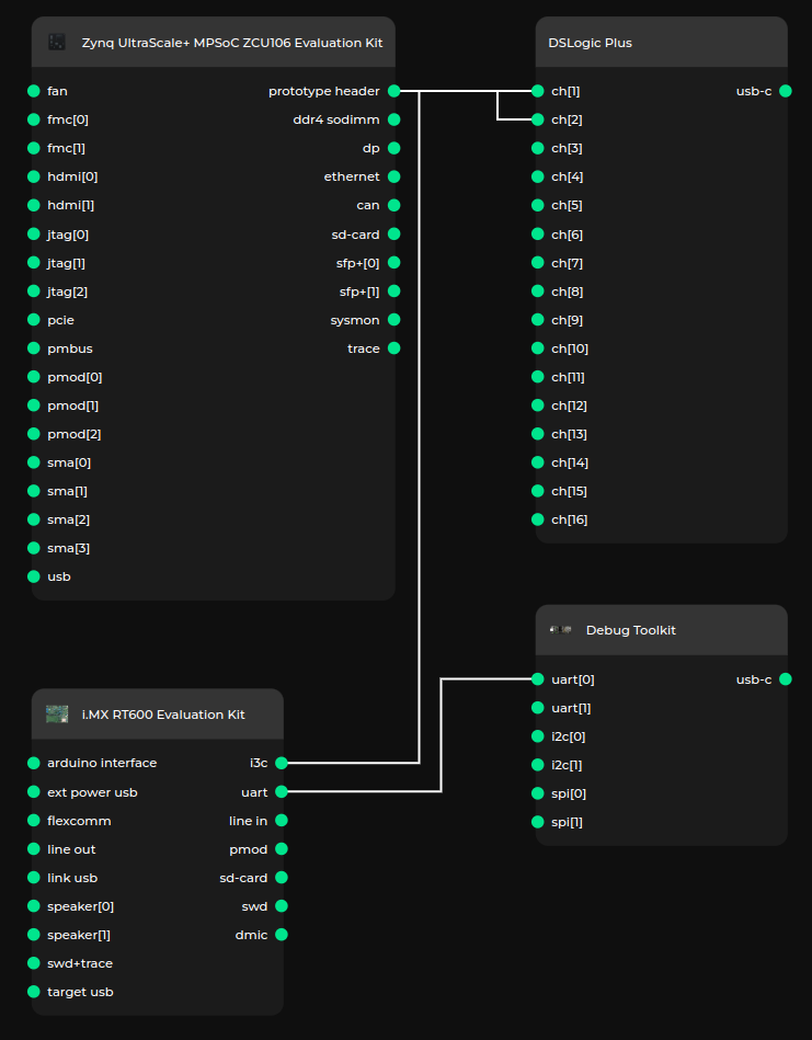
Test setup consists of:

Figure 18 Test setup diagram
AMD Zynq UltraScale+ MPSoC ZCU106 Evaluation Kit
The AMD Zynq UltraScale+ MPSoC ZCU106 Evaluation Kit is an evaluation board, on which we implemented the I3C Core.
The I3C bus is exposed on the J3 Prototype Header in LVCMOS18 IO standard.
Pin |
Signal |
J3.4 |
GND |
J3.8 (FPGA:L14)(L6P_AD6P_64_P) |
SDA |
J3.12 (FPGA:K14)(L5P_AD14P_64_P) |
SCL |
Info
SDA and SCL should be pulled up by external 2k\(\Omega\) resistors to 1.8V.
NXP i.MX RT600 Evaluation Kit
The NXP i.MX RT600 Evaluation Kit is a microcontroller development board with a hardware I3C controller. This board was selected, because it is supported in Zephyr. A Zephyr based application was developed for the testing purposes.
Warning
Make sure the NXP i.MX RT600 Evaluation Kit’s VDDIO1 is set to 1.8V (JP12 set to 1-2 position).
The I3C bus is exposed on J18 header.
Pin |
Signal |
J18.1 |
SCL (P2_29_I3C0_SCL) |
J18.2 |
SDA (P2_30_I3C0_SDA) |
J18.3 |
PUR (P2_31_I3C0_PUR) |
J18.4 |
GND |
Antmicro Debug Toolkit
Antmicro Debug Toolkit can be connected to NXP i.MX RT600 Evaluation Kit J16 UART header for debug purposes, e.g. Zephyr uses it for logging purposes.
Warning
Set jumper on appropriate channel voltage selector header, to select 3.3V IO voltage.
DreamSourceLab DSLogic Plus
DreamSourceLab DSLogic Plus is a 16 channel logic analyzer.
It allows for capturing 2 channels in buffer mode at 400MS/s for up to 335.54ms.
Measurement made with this tool are recorded with 2.5ns resolution.
Test procedure
After I3C initialization, the test procedure begins. The procedure consists of:
read_test
reading from selected I3C register
write_test
writing to the selected register
read_test
reading back from the selected register
ccc_test
reading configuration saved in controller (CONFIG)
sending direct CCC:
disabling events (DISEC)
reading Provisioned ID (GETPID)
reading Bus Characteristics Register (GETBCR)
reading Device Characteristics Register (GETDCR)
reading Maximum Read Length (GETMRL)
reading Maximum Write Length (GETMWL)
setting new dynamic address (SETNEWDA)
reading device status (GETSTATUS)
setting Maximum Read Length (SETMRL)
setting Maximum Write Length (SETMWL)
resetting dynamic address (RSTDAA broadcast)
setting device’s static address as the dynamic address (SETDASA)
enabling events (ENEC)
sending broadcast CCC:
disabling events (DISEC broadcast)
resetting I3C peripherals (RSTACT broadcast)
resetting dynamic addresses (RSTDAA broadcast)
setting static addresses as the dynamic addresses (SETAASA broadcast)
setting Maximum Read Lengths (SETMRL broadcast)
setting Maximum Write Lengths (SETMWL broadcast)
enabling events (ENEC broadcast)