Standby Controller
This chapter provides a description of the Standby Controller logic.
Standby Controller
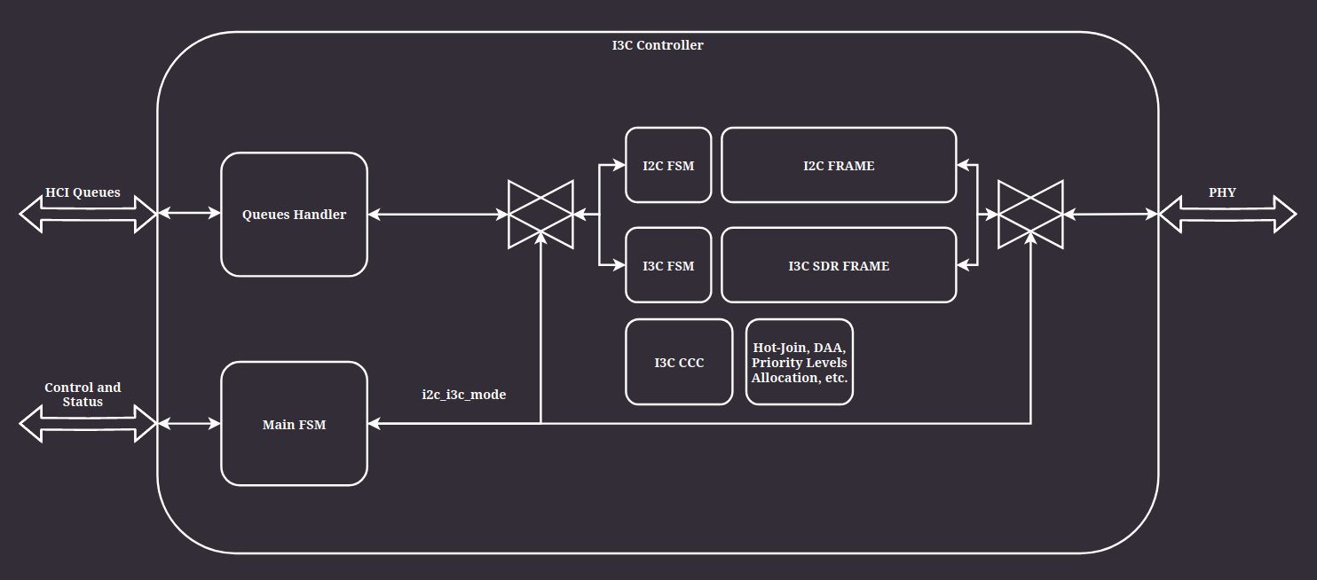
Main part of the system.

Figure 5 Block diagram of the I3C Controller
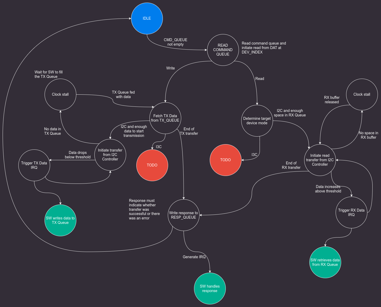
When the I3C Core acts as an Active Controller, it follows the flow presented in Figure 6.

Figure 6 FSM: Active Controller
Bus arbitration (5.1.2.2.1)
In an I3C (or multi-master I2C) system, it is possible that multiple devices connected to the bus will try to take over the bus control at the same time. An arbitration process must occur to resolve access. All devices that are concurrently transmitting an address follow the same rules:
If the current bit to transmit is a 0, then the Device will drive SDA Low after the falling edge of SCL and hold Low until the next falling edge of SCL.
Note
Other Devices may also be driving SDA Low, but that is acceptable.
If the current bit to transmit is a 1, then the Device will not drive SDA, but rather High-Z SDA on the falling edge of SCL.
Additionally, the Device will monitor the SDA on the rising edge of SCL to determine whether another Device has driven SDA Low.
If another Device has driven the SDA Low, then the Device has “lost” the Arbitration and will not further participate in this Address Header. That is, the Device will not transmit any more bits, but may wait for a future START (but not a Repeated START).
Note
Section 5.1.2.2.2 of the I3C specification describes possible arbitration enhancements.