Integration with Caliptra Subsystem
The I3C Controller is meant to be used as part of the Caliptra Subsystem.
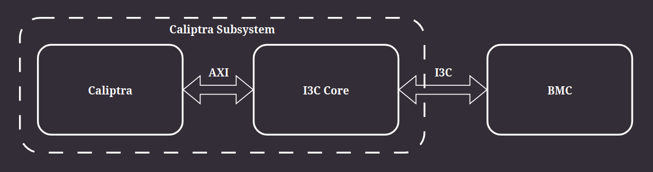
Figure 16 Integration of the I3C Core with Caliptra Subsystem in standard use case
Caliptra Subsystem
The Caliptra Subsystem is based on the Caliptra RTL but has trimmed functionalities and an embedded I3C Core. It consists of:
VeeR EL2 with DMA engine
SPI
I3C
HMAC
UART
SOC IFC
SHA256 & SHA512
ROM
All listed components are connected to an AHB Lite bus that is controlled by VeeR EL2 acting as a manager.
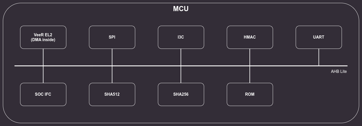
Figure 17 Caliptra Subsystem block diagram
Clock
The I3C core will be using the gated clk_cg clock, provided by the Caliptra-SS core.
Reset
The PON reset of the I3C core will be provided by the Caliptra-SS core.
The I3C core is responsive after PON release, so it does not provide a handshake (e.g. BOOT_DONE, RST_DONE, etc.)
Peripheral connection interface
The I3C Core can be connected as a subordinate on either AHB or AXI bus to enable both VeeR-EL2 configurations. The AHB/AXI interface is connected to an adapter, which enables access to the Control and Status Registers. SystemVerilog CSR description is generated with PeakRDL and uses the “Internal CPUIF Protocol”.
Controller Interface test
In test smoke_test_i3c.c, the I3C Core is connected via an AHB bus to the Caliptra SubSystem.
Communication with internal registers of the I3C Core is executed by using the lsu_write_32() and lsu_read_32() functions from the riscv_hw_if.h Caliptra header.
Software is executed on the simulated VeeR-EL2 core.
The software test executes read/write operations on different configurations of registers to check whether RTL generated from the RDL configuration behaves properly from the software point of view.
Interrupts
Calitpra specifies required interface for interrupts which consists of two aggregator single bit signals:
error_intr_o- error interrupts assigned a higher priority and expected to be infrequent,notif_intr_o- alert the processor of normal operation activity, such as completion of requested operations or arrival of SoC requests through the shared interface.
Register group |
Register name |
Field name |
Description |
Type |
HCI Base registers |
INTR_STATUS |
SCHED_CMD_MISSED_TICK_STAT |
Scheduled commands could be executed due to controller being busy |
Notification |
HCI Base registers |
INTR_STATUS |
HC_ERR_CMD_SEQ_TIMEOUT_STAT |
Command timeout after prolonged stall |
Error |
HCI Base registers |
INTR_STATUS |
HC_WARN_CMD_SEQ_STALL_STAT |
Clock stalled due to lack of commands |
Notification |
HCI Base registers |
INTR_STATUS |
HC_SEQ_CANCEL_STAT |
Controller had to cancel command sequence |
Notification |
HCI Base registers |
INTR_STATUS |
HC_INTERNAL_ERR_STAT |
Controller internal unrecoverable error |
Error |
HCI PIO registers |
PIO_INTR_STATUS |
TRANSFER_ERR_STAT |
Transfer error |
Error |
HCI PIO registers |
PIO_INTR_STATUS |
TRANSFER_ABORT_STAT |
Transfer aborted |
Notification |
HCI PIO registers |
PIO_INTR_STATUS |
RESP_READY_STAT |
Response queue fulfils RESP_BUF_THLD |
Notification |
HCI PIO registers |
PIO_INTR_STATUS |
CMD_QUEUE_READY_STAT |
Command queue fulfils CMD_EMPTY_BUF_THLD |
Notification |
HCI PIO registers |
PIO_INTR_STATUS |
IBI_STATUS_THLD_STAT |
IBI queue fulfils IBI_STATUS_THLD |
Notification |
HCI PIO registers |
PIO_INTR_STATUS |
RX_THLD_STAT |
RX queue fulfils RX_BUF_THLD |
Notification |
HCI PIO registers |
PIO_INTR_STATUS |
TX_THLD_STAT |
TX queue fulfils TX_BUF_THLD |
Notification |
TTI registers |
INTERRUPT_STATUS |
TRANSFER_ERR_STAT |
Bus error occurred |
Error |
TTI registers |
INTERRUPT_STATUS |
TRANSFER_ABORT_STAT |
Bus aborted transaction |
Notification |
TTI registers |
INTERRUPT_STATUS |
IBI_THLD_STAT |
TTI IBI Buffer Threshold Status, the Target Controller shall set this bit to 1 when the number of available entries in the TTI IBI Queue is >= the value defined in |
Notification |
TTI registers |
INTERRUPT_STATUS |
RX_DESC_THLD_STAT |
TTI RX Descriptor Buffer Threshold Status, the Target Controller shall set this bit to 1 when the number of available entries in the TTI RX Descriptor Queue is >= the value defined in |
Notification |
TTI registers |
INTERRUPT_STATUS |
TX_DESC_THLD_STAT |
TTI TX Descriptor Buffer Threshold Status, the Target Controller shall set this bit to 1 when the number of available entries in the TTI TX Descriptor Queue is >= the value defined in |
Notification |
TTI registers |
INTERRUPT_STATUS |
RX_DATA_THLD_STAT |
TTI RX Data Buffer Threshold Status, the Target Controller shall set this bit to 1 when the number of entries in the TTI RX Data Queue is >= the value defined in |
Notification |
TTI registers |
INTERRUPT_STATUS |
TX_DATA_THLD_STAT |
TTI TX Data Buffer Threshold Status, the Target Controller shall set this bit to 1 when the number of available entries in the TTI TX Data Queue is >= the value defined in |
Notification |
TTI registers |
INTERRUPT_STATUS |
TX_DESC_TIMEOUT |
Pending Write was NACK’ed, because the |
Error |
TTI registers |
INTERRUPT_STATUS |
RX_DESC_TIMEOUT |
Pending Read was NACK’ed, because the |
Error |
TTI registers |
INTERRUPT_STATUS |
TX_DESC_STAT |
There is a pending Write Transaction on the I3C Bus. Software should write data to the TX Descriptor Queue and the TX Data Queue |
Notification |
TTI registers |
INTERRUPT_STATUS |
RX_DESC_STAT |
There is a pending Read Transaction. Software should read data from the RX Descriptor Queue and the RX Data Queue |
Notification |
Target Device Provisioned ID
The integrator should update pid_hi parameter in the src/rdl/registers.rdl to valid MIPI Manufacturer ID:
bit pid_hi = 0xFF, // Vendor-specific values