| @@ -1,75 +1,309 @@ |
| 1 | 1 | <div style="font-size: 0.85em; color: #656d76; margin-bottom: 1em; padding: 0.5em; background: #f6f8fa; border-radius: 4px;"> |
| 2 | | -📄 Source: <a href="https://github.com/chipsalliance/i3c-core/blob/aae3424a8ecbd4edb7a60e23f76421de2d891712/doc/source/axi_recovery_flow.md" target="_blank">chipsalliance/i3c-core/doc/source/axi_recovery_flow.md</a> @ <code>aae3424</code> |
| 2 | +📄 Source: <a href="https://github.com/chipsalliance/i3c-core/blob/01b3839e17cc367f524fddd488c013c82374e149/doc/source/axi_recovery_flow.md" target="_blank">chipsalliance/i3c-core/doc/source/axi_recovery_flow.md</a> @ <code>01b3839</code> |
| 3 | 3 | </div> |
| 4 | 4 | |
| 5 | | -# AXI driven Caliptra recovery flow |
| 6 | | - |
| 7 | | -This chapter discusses the implementation of AXI based recovery flow, which is an alternative to the standard I3C based flow (see [recovery_flow](recovery_flow.md)). |
| 8 | | -This feature allows driving the recovery data from within the SoC integrating the I3C core over the AXI bus, bypassing I3C communication. |
| 9 | | - |
| 10 | | -## AXI Recovery flow implementation |
| 11 | | - |
| 12 | | -The AXI recovery flow reuses the logic already present in the I3C core used in the Caliptra-SS design, with a runtime option essentially bypassing most of the I3C core communication logic (including the I3C recovery flow logic). |
| 13 | | - |
| 14 | | -The loopback functionality is configurable via a CSR, with the I3C mode set as the default. |
| 15 | | - |
| 16 | | -Recovery CSRs are accessible from the internal AXI bus. |
| 17 | | -The transactions to the core may be filtered using the AXI ID field (see [axi_id_filtering](axi_id_filtering.md)) |
| 18 | | - |
| 19 | | -The logic is implemented so that the recovery firmware in the Caliptra RoT ROM can operate without any changes. |
| 20 | | - |
| 21 | | -### AXI-based recovery procedure |
| 22 | | - |
| 23 | | -The Caliptra MCU RISC-V core is responsible for driving the data copied from an external memory (e.g. QSPI interface) to the recovery FIFOs. |
| 24 | | -The ROM running on the MCU core monitors the recovery block registers and performs the recovery flow. |
| 25 | | -During the boot procedure the ROM will have to follow the following procedure: |
| 26 | | - |
| 27 | | -1. Set the I3C block to the "direct AXI" mode |
| 28 | | -2. Poll the `DEVICE_STATUS` register and wait for the recovery to be enabled by the Caliptra core |
| 29 | | -3. Read the `RECOVERY_STATUS` register and check if the recovery flow started |
| 30 | | -4. Write to the `RECOVERY_CONTROL` register to set the recovery image configuration |
| 31 | | -5. Write to the `INDIRECT_FIFO_CTRL` register to set the recovery image size |
| 32 | | -6. Push the recovery image to the recovery interface FIFOs: |
| 33 | | - |
| 34 | | - a. Read the `INDIRECT_FIFO_STATUS` register to determine remaining space in the indirect FIFO |
| 35 | | - b. If the indirect FIFO is not full, write a chunk of data to the `INDIRECT_FIFO_DATA` register |
| 36 | | - c. The above steps should be repeated until the whole recovery image is written to the FIFO |
| 37 | | - |
| 38 | | -7. Activate the new image by writing to the `RECOVERY_CTRL` register |
| 39 | | -8. Read the `RECOVERY_STATUS` register to ensure the image has been activated |
| 40 | | - |
| 41 | | -The recovery image will be written in chunks with length equal to or less than `Max transfer size` defined in the `INDIRECT_FIFO_STATUS` register. |
| 42 | | -Once the last data chunk is written to the FIFO, the Caliptra MCU ROM will write a CSR in the Secure Firmware Recovery register file indicating the transfer is complete. |
| 43 | | - |
| 44 | | -## Recovery Handler bypass |
| 45 | | - |
| 46 | | -In the regular (I3C) mode of the core, the Recovery Handler strongly relies on communication with the I3C Core internal logic by interfacing with TTI Queues. |
| 47 | | -The bypass implementation modifies the I3C Core logic to allow direct access over the AXI bus to the structures specified by the OCP Secure Firmware Recovery for compliance with the [Caliptra Subsystem Recovery Sequence](https://github.com/chipsalliance/Caliptra/blob/main/doc/Caliptra.md#caliptra-subsystem-recovery-interface-hardware). |
| 48 | | - |
| 49 | | -The default design of the Recovery Handler includes many blocks specifically designed to translate I3C bus traffic into recovery messages. |
| 50 | | -It also automatically responds to the I3C commands by writing transaction descriptors and data for the TTI Queues. |
| 51 | | -Such a recovery flow is presented in the diagram below. |
| 5 | +# AXI Recovery Flow |
| 6 | + |
| 7 | +This chapter describes the AXI-based firmware recovery flow, which allows |
| 8 | +driving recovery data from within the SoC over the AXI bus, bypassing I3C |
| 9 | +communication. For the standard I3C-based recovery flow, see [recovery_flow](recovery_flow.md). |
| 10 | + |
| 11 | +## Overview |
| 12 | + |
| 13 | +The recovery flow transfers firmware images from an external source through |
| 14 | +the I3C core's Indirect FIFO to the Device Firmware. Three actors participate: |
| 15 | + |
| 16 | +| Actor | Role | |
| 17 | +| ------- | ------ | |
| 18 | +| **Image Provider** | SoC-internal firmware that reads images from storage and writes them to `TTI_TX_DATA_PORT` via AXI (the hardware routes these writes into the Indirect FIFO when bypass mode is enabled) | |
| 19 | +| **I3C Core** | Hosts the OCP recovery registers and Indirect FIFO | |
| 20 | +| **Device Firmware** | Reads images from the Indirect FIFO, validates, and boots them | |
| 21 | + |
| 22 | + |
| 23 | +The Image Provider and Device Firmware operate **concurrently** and synchronize |
| 24 | +through shared OCP recovery registers in the I3C core. |
| 25 | + |
| 26 | +## Prerequisite |
| 27 | + |
| 28 | +Enable AXI bypass mode before starting recovery: |
| 29 | + |
| 30 | +``` |
| 31 | +REC_INTF_CFG.REC_INTF_BYPASS = 1 |
| 32 | +``` |
| 33 | + |
| 34 | +This routes data directly from the AXI bus to the Indirect FIFO, bypassing |
| 35 | +the I3C protocol logic. The Device Firmware operates identically in both I3C |
| 36 | +and AXI bypass modes. |
| 37 | + |
| 38 | +```{warning} |
| 39 | +Once set, `REC_INTF_BYPASS` must not be cleared until the next system |
| 40 | +reset. This is a one-time configuration for the life of the reset domain. |
| 41 | +``` |
| 42 | + |
| 43 | +## Multi-Stage Recovery Flow |
| 44 | + |
| 45 | +The recovery flow transfers one or more images in sequence. Each image is |
| 46 | +identified by a `REC_IMG_INDEX` value. The number of stages and their content |
| 47 | +are platform-defined. A typical three-stage example: |
| 48 | + |
| 49 | +| Stage | REC_IMG_INDEX | Description | |
| 50 | +| ------- | --------------- | ------------- | |
| 51 | +| 0 | 0x0 | Primary firmware image | |
| 52 | +| 1 | 0x1 | Configuration / manifest | |
| 53 | +| 2 | 0x2 | Application firmware | |
| 54 | + |
| 55 | + |
| 56 | +Each stage follows the same handshake protocol. The timeline below shows the |
| 57 | +interleaved register operations between the Image Provider and Device Firmware |
| 58 | +for a single stage. Steps marked with the same number happen concurrently. |
| 59 | + |
| 60 | +### Per-Stage Timeline |
| 61 | + |
| 62 | +``` |
| 63 | + Image Provider I3C Core Regs Device Firmware |
| 64 | + -------------- ------------- --------------- |
| 65 | + | | | |
| 66 | + | | 1. Write PROT_CAP |
| 67 | + | | (recovery caps) |
| 68 | + | | | |
| 69 | + | | 2. Write DEVICE_STATUS_0 |
| 70 | + | | .DEV_STATUS = 0x3 |
| 71 | + | | (recovery mode) |
| 72 | + | | | |
| 73 | + | | 3. Write RECOVERY_STATUS |
| 74 | + | | .DEV_REC_STATUS = 0x1 |
| 75 | + | | .REC_IMG_INDEX = <stage> |
| 76 | + | | (awaiting image) |
| 77 | + | | | |
| 78 | + | | 3a. Wait for payload_available_o |
| 79 | + | | to deassert (no-op on first |
| 80 | + | | stage; on subsequent stages |
| 81 | + | | waits for Image Provider to |
| 82 | + | | clear REC_PAYLOAD_DONE at |
| 83 | + | | step 17) |
| 84 | + | | | |
| 85 | + 4. Read PROT_CAP_2 | | |
| 86 | + verify recovery capability | | |
| 87 | + | | | |
| 88 | + 5. Poll DEVICE_STATUS_0 | | |
| 89 | + until DEV_STATUS == 0x3 | | |
| 90 | + | | | |
| 91 | + 6. Poll RECOVERY_STATUS | | |
| 92 | + until DEV_REC_STATUS == 0x1 | | |
| 93 | + Read REC_IMG_INDEX to determine | | |
| 94 | + which image Device Firmware expects | | |
| 95 | + | | | |
| 96 | + 7. Write INDIRECT_FIFO_CTRL_1 | | |
| 97 | + .IMAGE_SIZE = image size in 4B | | |
| 98 | + units (i.e. byte count / 4) | | |
| 99 | + | | | |
| 100 | + v | | |
| 101 | + ,-------------------------------. | | |
| 102 | + | 8. DATA TRANSFER LOOP | | | |
| 103 | + | (Provider writes, | | | |
| 104 | + | Device FW reads) | | | |
| 105 | + `-------------------------------' | | |
| 106 | + | | | |
| 107 | + | Poll FIFO_STATUS_0.EMPTY | DMA triggered by | |
| 108 | + | Write chunk to TTI_TX_DATA_PORT | payload_available_o | |
| 109 | + | (max transfer size per chunk) | (reads FIFO_SIZE or | |
| 110 | + | | remaining bytes) | |
| 111 | + | ... repeat until all data transferred ... | |
| 112 | + | | | |
| 113 | + 9. Write REC_INTF_CFG | | |
| 114 | + .REC_PAYLOAD_DONE = 1 | | |
| 115 | + (signal last chunk sent) | | |
| 116 | + | | | |
| 117 | + | | 10. Write DEVICE_STATUS_0 |
| 118 | + | | .DEV_STATUS = 0x4 |
| 119 | + | | (recovery pending) |
| 120 | + | | | |
| 121 | + | | 11. Poll RECOVERY_CTRL |
| 122 | + | | .ACTIVATE_REC_IMG |
| 123 | + | | until == 0xF |
| 124 | + | | | |
| 125 | + 12. Poll DEVICE_STATUS_0 | | |
| 126 | + until DEV_STATUS == 0x4 | | |
| 127 | + (Device FW finished reading, | | |
| 128 | + waiting for activation) | | |
| 129 | + | | | |
| 130 | + 13. Write REC_INTF_REG_W1C_ACCESS | | |
| 131 | + .RECOVERY_CTRL_ACTIVATE_REC_IMG | | |
| 132 | + = 0xF (triggers image_activated_o) | | |
| 133 | + | | | |
| 134 | + | | 14. Write DEV_REC_STATUS = 0x2 |
| 135 | + | | (processing image) |
| 136 | + | | | |
| 137 | + 15. Poll DEVICE_STATUS_0.DEV_STATUS | | |
| 138 | + Wait while DEV_STATUS == 0x4 | | |
| 139 | + (Device FW is validating the image) | | |
| 140 | + | | | |
| 141 | + | | 16. Validate image |
| 142 | + | | (crypto verification) |
| 143 | + | | | |
| 144 | + | | [Intermediate, on success] |
| 145 | + | | Clear ACTIVATE_REC_IMG |
| 146 | + | | Reset INDIRECT_FIFO_CTRL_0 |
| 147 | + | | -> loop back to step 2 |
| 148 | + | | (with next REC_IMG_INDEX) |
| 149 | + | | | |
| 150 | + | | [On error (any stage)] |
| 151 | + | | Write DEV_REC_STATUS >= 0xc |
| 152 | + | | Write DEV_STATUS = 0xF |
| 153 | + | | | |
| 154 | + | | [Final stage, on success] |
| 155 | + | | Write DEV_REC_STATUS = 0x3 |
| 156 | + | | Write DEV_STATUS = 0x1 |
| 157 | + | | (recovery successful, |
| 158 | + | | device healthy) |
| 159 | + | | | |
| 160 | + 17. DEV_STATUS changed from 0x4: | | |
| 161 | + 0x3 = next stage ready | | |
| 162 | + Clear REC_INTF_CFG | | |
| 163 | + .REC_PAYLOAD_DONE = 0 | | |
| 164 | + -> go back to step 5 | | |
| 165 | + 0x1 = recovery complete | | |
| 166 | + -> exit | | |
| 167 | + 0xF = error | | |
| 168 | + -> abort recovery | | |
| 169 | + | | | |
| 170 | +``` |
| 171 | + |
| 172 | +### Stage-Specific Details |
| 173 | + |
| 174 | +**Intermediate stages:** |
| 175 | +- Device Firmware validates the received image (e.g. crypto verification) |
| 176 | +- On success, Device Firmware clears `ACTIVATE_REC_IMG`, resets the |
| 177 | + Indirect FIFO via `INDIRECT_FIFO_CTRL_0.RESET`, and loops back to |
| 178 | + step 2 (writing the next `REC_IMG_INDEX`) |
| 179 | +- After writing `RECOVERY_STATUS` at step 3, Device Firmware must wait |
| 180 | + for `payload_available_o` to deassert before polling for new payload. |
| 181 | + This avoids a race where stale `REC_PAYLOAD_DONE` from the prior |
| 182 | + stage keeps `payload_available_o` asserted, causing Device Firmware |
| 183 | + to read the old `IMAGE_SIZE`. The Image Provider clears |
| 184 | + `REC_PAYLOAD_DONE` at step 17, which deasserts |
| 185 | + `payload_available_o`. |
| 186 | +- Image Provider detects `DEV_REC_STATUS == 0x1` at step 17 and loops |
| 187 | + back to step 5 |
| 188 | + |
| 189 | +**Final stage:** |
| 190 | +- Same data transfer handshake as intermediate stages |
| 191 | +- On success, Device Firmware writes `DEV_REC_STATUS = 0x3` (recovery |
| 192 | + successful) and `DEV_STATUS = 0x1` (device healthy) |
| 193 | +- On error, Device Firmware writes `DEV_REC_STATUS >= 0xc` and |
| 194 | + `DEV_STATUS = 0xF` |
| 195 | +- Image Provider detects `DEV_REC_STATUS == 0x3` at step 17 and exits |
| 196 | + |
| 197 | +```{important} |
| 198 | +**Intermediate stage completion**: For all stages except the final one, |
| 199 | +Device Firmware clears `ACTIVATE_REC_IMG`, resets the Indirect FIFO via |
| 200 | +`INDIRECT_FIFO_CTRL_0.RESET`, and loops back to step 2 to signal |
| 201 | +readiness for the next image. The FIFO reset is performed by Device |
| 202 | +Firmware, not the Image Provider. Device Firmware writes `DEV_STATUS = 0x3` |
| 203 | +last (at step 2), after all cleanup is complete. |
| 204 | + |
| 205 | +**`REC_PAYLOAD_DONE` ownership**: The Image Provider owns the |
| 206 | +`REC_INTF_CFG.REC_PAYLOAD_DONE` bit. It sets the bit after the last |
| 207 | +chunk of each image (step 9) and clears it at step 17 when |
| 208 | +`DEV_STATUS` transitions away from 0x4 (before looping back to step 5). |
| 209 | +Between stages, `payload_available_o` may remain asserted because |
| 210 | +`REC_PAYLOAD_DONE` is still set from the prior stage. |
| 211 | +Device Firmware must wait for `payload_available_o` to deassert after |
| 212 | +writing `RECOVERY_STATUS` (step 3) and before polling for new payload. |
| 213 | +This wait ensures the Image Provider has cleared `REC_PAYLOAD_DONE` |
| 214 | +and the new `IMAGE_SIZE` is valid. Failure to perform this wait can |
| 215 | +cause Device Firmware to read a stale image size and set up DMA |
| 216 | +transfers with the wrong byte count. |
| 217 | + |
| 218 | +**Final stage completion**: After the final stage, Device Firmware |
| 219 | +writes `DEV_REC_STATUS = 0x3` (recovery successful) and |
| 220 | +`DEV_STATUS = 0x1` (device healthy). The Image Provider polls for |
| 221 | +this transition at step 15/17 to confirm recovery is complete. |
| 222 | +``` |
| 223 | + |
| 224 | +```{note} |
| 225 | +Once `REC_INTF_BYPASS` is set to 1, it must not be cleared until the |
| 226 | +next system reset. The bypass setting is effectively a one-time |
| 227 | +configuration for the life of the reset domain. FW must not write |
| 228 | +`REC_INTF_BYPASS = 0` after recovery completes. |
| 229 | +``` |
| 230 | + |
| 231 | +### Authentication Error Handling |
| 232 | + |
| 233 | +If Device Firmware fails to authenticate a pushed image at any stage, it |
| 234 | +writes an error status to `RECOVERY_STATUS.DEV_REC_STATUS` (>= 0xc) and |
| 235 | +sets `DEVICE_STATUS_0.DEV_STATUS = 0xF`. The recovery flow terminates |
| 236 | +immediately -- no further stages are executed. See OCP Recovery v1.1 |
| 237 | +Section 7.6 for the full list of `DEV_REC_STATUS` error codes. |
| 238 | + |
| 239 | +The Image Provider should check for error status (`DEV_STATUS == 0xF`) |
| 240 | +at step 15 of each stage. If an error is detected, the Image Provider |
| 241 | +should terminate the recovery flow. No retry is attempted. |
| 242 | + |
| 243 | +```{note} |
| 244 | +The Image Provider should not poll indefinitely for a success status |
| 245 | +without also checking for error conditions. Device Firmware may report |
| 246 | +an authentication or activation error at any stage. An Image Provider |
| 247 | +that only polls for DEV_STATUS == 0x3 (next stage) or == 0x1 (success) |
| 248 | +will hang if Device Firmware writes DEV_STATUS = 0xF instead. |
| 249 | +``` |
| 250 | + |
| 251 | +## Register Reference |
| 252 | + |
| 253 | +Recovery registers are part of the Secure Firmware Recovery Interface |
| 254 | +extended capability. See {ref}`tab-secure-firmware-recovery-interface` in |
| 255 | +[ext_cap](ext_cap.md) for the full register list and field descriptions. |
| 256 | + |
| 257 | +The AXI bypass flow also uses two registers from the SoC Management Interface: |
| 258 | + |
| 259 | +- `REC_INTF_CFG.REC_INTF_BYPASS` -- enables AXI bypass mode |
| 260 | +- `REC_INTF_CFG.REC_PAYLOAD_DONE` -- signals last chunk written |
| 261 | +- `REC_INTF_REG_W1C_ACCESS` -- sideband write path for `RECOVERY_CTRL` |
| 262 | + and `INDIRECT_FIFO_CTRL` (needed because AXI bypass skips the I3C |
| 263 | + Recovery Handler that normally writes these registers) |
| 264 | + |
| 265 | +## Data Transfer Constraints |
| 266 | + |
| 267 | +- Maximum chunk size per FIFO write is defined by `INDIRECT_FIFO_STATUS_4` |
| 268 | +- Image Provider must poll `INDIRECT_FIFO_STATUS_0.EMPTY` after each chunk to |
| 269 | + ensure Device Firmware has drained the FIFO before writing the next chunk |
| 270 | +- Device Firmware uses `recovery_payload_available_o` as a DMA trigger. |
| 271 | + Each assertion of `payload_available_o` signals that the Indirect FIFO |
| 272 | + contains a complete chunk (or the final partial chunk) ready for reading. |
| 273 | + The DMA reads either the full FIFO contents or, for the last chunk of an |
| 274 | + image, only the remaining bytes. Once the DMA drains the FIFO, |
| 275 | + `payload_available_o` deasserts and the DMA waits for the next assertion. |
| 276 | +- `payload_available_o` asserts in bypass mode when the Indirect FIFO is |
| 277 | + full, `REC_PAYLOAD_DONE` is set, or the image has been activated. It |
| 278 | + deasserts when the FIFO is empty. |
| 279 | +- `REC_PAYLOAD_DONE` must be set after the last chunk (step 9) and |
| 280 | + cleared by the Image Provider at step 17 when transitioning to the |
| 281 | + next stage. Device Firmware must not poll `payload_available_o` for |
| 282 | + a new image until it observes `payload_available_o` deassert, |
| 283 | + confirming the Image Provider has cleared `REC_PAYLOAD_DONE`. |
| 284 | + |
| 285 | +## AXI Bypass Architecture |
| 286 | + |
| 287 | +In the default I3C mode, the Recovery Handler translates I3C bus traffic into |
| 288 | +recovery register accesses. The bypass feature routes AXI writes directly to |
| 289 | +the Indirect FIFO, disabling the I3C communication logic. |
| 52 | 290 | |
| 53 | 291 | :::{figure-md} recovery_handler |
| 54 | 292 | 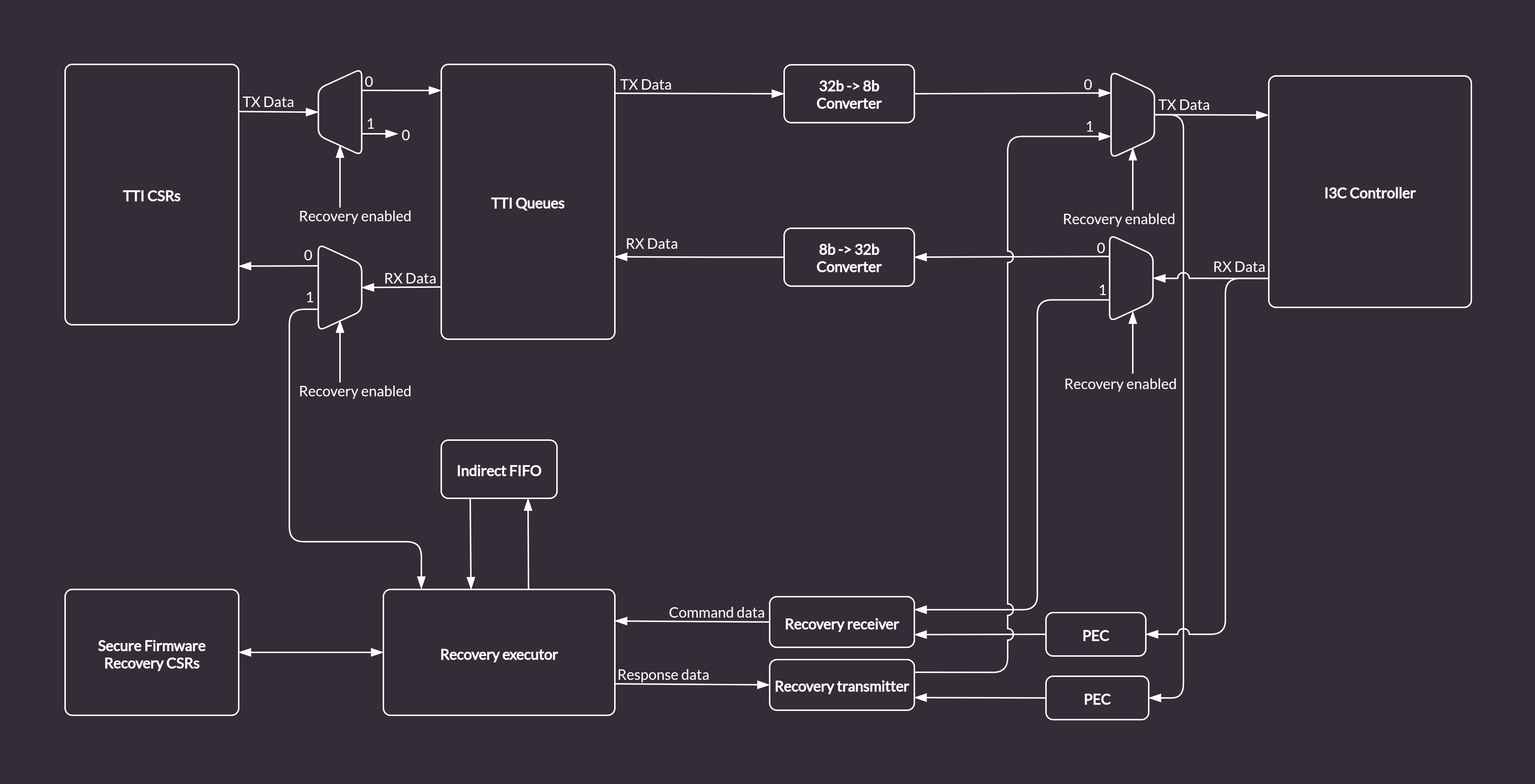 |
| 55 | 293 | |
| 56 | | -Recovery Handler in the I3C Core |
| 294 | +Recovery Handler in the I3C Core (standard I3C mode) |
| 57 | 295 | ::: |
| 58 | 296 | |
| 59 | | -In order enable an alternative recovery mechanism while reusing the existing logic and keeping compliance with Caliptra, the I3C core provides a custom bypass feature allowing direct communication with the Recovery Handler via the AXI bus. |
| 60 | | -The bypass disables the I3C communication logic. |
| 61 | | -Data is routed from the TTI TX Queue to the Recovery Executor block, and written directly to the Indirect Data FIFO. |
| 62 | | -The Caliptra ROM can access the data from the Indirect FIFO over the AXI bus (the same way it does in the regular I3C recovery flow). |
| 63 | | -Data flow in bypass mode, marked with green arrows, is depicted in the diagram below. |
| 297 | +With bypass enabled, Image Provider writes to `TTI_TX_DATA_PORT` over AXI. |
| 298 | +The hardware forwards those writes through the TTI TX Queue into the Indirect |
| 299 | +Data FIFO. Device Firmware reads from the Indirect FIFO over AXI identically |
| 300 | +to the I3C flow. |
| 64 | 301 | |
| 65 | 302 | :::{figure-md} recovery_handler_with_bypass |
| 66 | 303 | 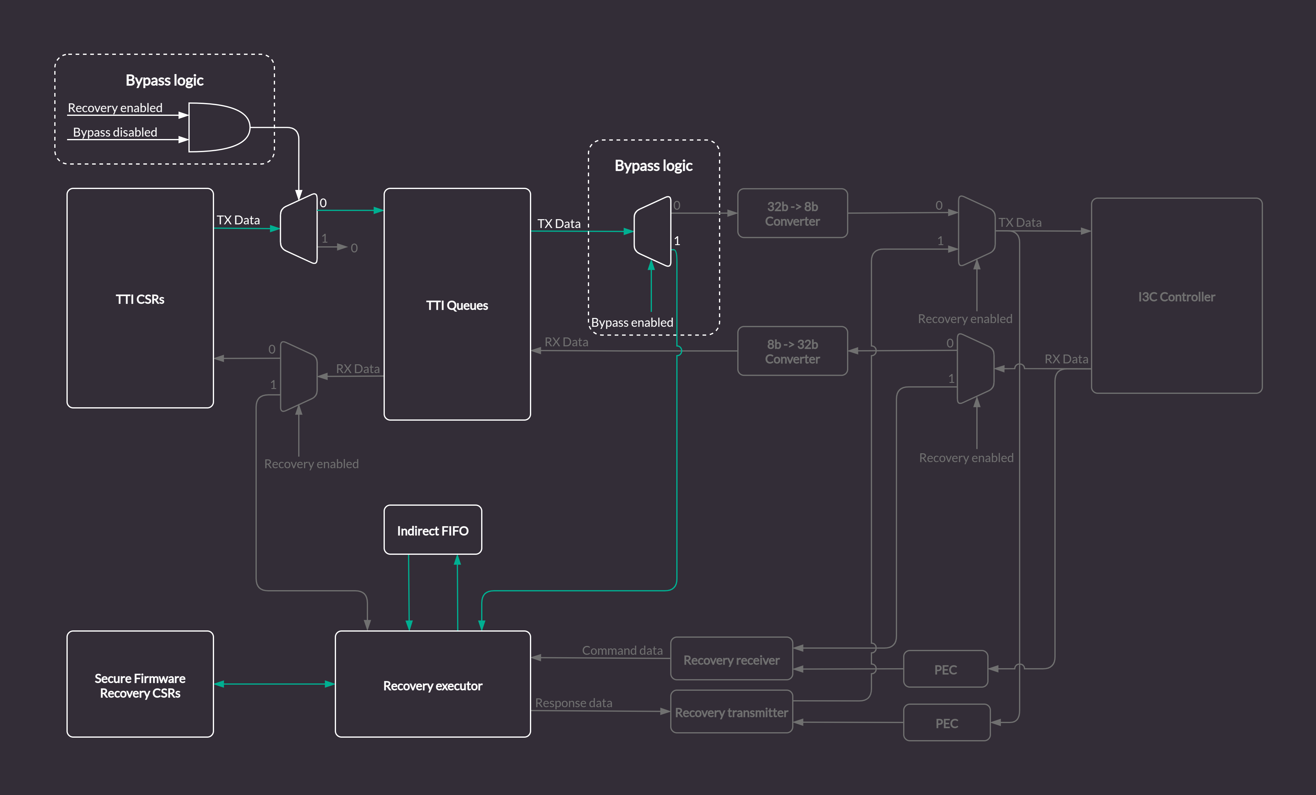 |
| 67 | 304 | |
| 68 | | -Recovery Handler with the I3C Core logic bypass |
| 305 | +Recovery Handler with AXI bypass (green arrows show bypass data path) |
| 69 | 306 | ::: |
| 70 | 307 | |
| 71 | | -## Secure Firmware Recovery CSRs |
| 72 | | - |
| 73 | | -With the bypass feature enabled, the FIFO status CSRs in the Secure Firmware Recovery CSR file will be updated by the Recovery Handler module. |
| 74 | | -However, some registers like e.g. `INDIRECT_FIFO_CTRL` which are updated by I3C commands in a standard recovery flow, will have to be accessed and configured properly from the software running on the Caliptra MCU via the AXI bus. |
| 75 | | -All configurable registers are writable from software, read only registers provide status information about Recovery Handler internals, e.g. details about size and fill level of the Indirect FIFO. |
| 308 | +AXI transactions may be filtered using the AXI ID field |
| 309 | +(see [axi_id_filtering](axi_id_filtering.md)). |